¶ About This Manual
Thank you for your purchase and welcome to the SuperGY6 AC+ V4.1 User Manual. Please read the manual before your first use to ensure you use this product correctly and safely.

The next 10 minutes you invest in reading this page can save you from the most common mistakes people make when starting out with GY6 wiring and electronics. Reading all the way through can dramatically lower your chances of problems, help maximize the lifespan of your electrical system, and help outline how to approach the electrical system in a way that works well long term.
¶ Product Support Scope
Documentation scope: This manual focuses on practical information related to the specific SuperGY6 wiring harness you've purchased and the optional parts kit. It does not attempt to explain existing factory components or every system on your vehicle, especially parts not offered or sold here.
Support messaging scope: Similarly, support messages may be limited to the product you purchased and related installation or usage guidance. We cannot provide full training or diagnostics for every factory component, vehicle variation, or system not offered or sold here.
For questions about factory components, vehicle-specific troubleshooting, or service procedures outside this harness and kit, consult the service manual for your vehicle.
¶ Important Warnings
⛔ During engine operation or troubleshooting, DON'T touch the spark plug, ignition coil wire or boot, or the ignition coil leads. These surfaces can shock you, and contact should be avoided.
⛔ If you are not getting spark, DON'T modify the harness with extra grounds, and DO NOT disable the kill switch. Follow the recommended steps below to find and solve ignition problems.
⛔ DON'T add any ground wires to the vehicle frame. Grounds go to the engine crankcase only. Chassis grounds are a mistake on these machines and a leading cause of troubleshooting confusion.
¶ Install Instructions
This label comes printed on every SuperGY6 AC+ harness package. Go ahead and save a copy.
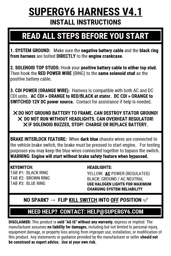
¶ Power and Ground
¶ 1. Ground (BLACK)
KEEP ALL GROUNDS CONNECTED TO THE CRANKCASE, ESPECIALLY THE NEGATIVE BATTERY CABLE.
Failure to connect the negative battery cable directly to the crankcase is a leading cause of harness damage. It is important to do your grounds correctly and avoid contradictory advice online suggesting that you can cut corners with your grounds.
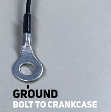
Example of ground-related damage. When the negative battery cable is connected to the frame instead of directly to the crankcase, starter current can try to return through the smaller stator ground wire, which was never designed to carry that load. The result can be melted insulation, burned wiring, and confusing electrical problems.
Some GY6 vehicles come with factory ground cables attached to the frame, then jumpered to the crankcase. This can, and has, resulted in severe problems on factory electrical systems when that small jumper link vibrates loose and loses contact at either end. For that reason, it is best to make ground attachments directly at the crankcase.
If any factory ground cables are connected to the frame through a short jumper segment, remove the jumper and reattach the negative battery cable directly to the crankcase. Do the same for anything else a previous owner may have grounded to the frame.
Accessory grounds may be tied together at the front of the vehicle, then joined into one wire of suitable size and ampacity that connects that ground point back to the crankcase.
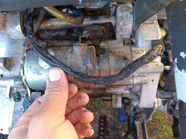
¶ 2. Power (RED)
The SuperGY6 harness doesn't connect directly to the battery. The harness connects to 12-volt DC power at the solenoid and reaches the battery through your existing battery cable. This keeps wiring clean and easy to maintain.
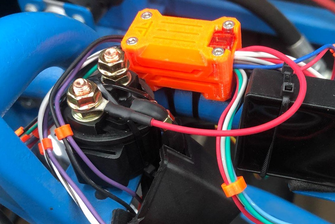
Not sure where the ring goes? Start with the picture below to make it easy. After mounting the solenoid and harness in place, mock up the red ring on either solenoid stud. It does not matter which stud you start with. Just mock up the connections for now; don't tighten the studs until instructed to do so below.
Then, mock-fit your POSITIVE BATTERY CABLE below the red harness wire on the SAME STUD.
Finally, mock-fit your STARTER CABLE on the second empty solenoid stud. It should be all by itself.
⚠️ BEFORE PROCEEDING - DO NOT OVER-TIGHTEN THE SOLENOID STUDS!
THE SOLENOID AND ITS LIFESPAN CAN BE IMMEDIATELY DAMAGED IF THE STUD NUTS ARE OVER-TORQUED. The studs are anchored in a plastic housing for electrical isolation. If you use a single wrench on the top nut only, excessive force will be applied to the plastic areas. This can force the stud to rotate slightly, breaking its factory position and internal alignment. This can, and often does, reduce the lifespan of the solenoid to just days or even hours.
Instead, use two wrenches when tightening the studs: one wrench to hold the bottom nut while using the second wrench to tighten the top nut onto the cables. This keeps force local to the metal stud and nuts, avoiding stress on the plastic housing.
With that understanding, now use TWO 10MM WRENCHES to carefully tighten down the stud nuts on their respective cables.
Congrats, power is done ✅
Additional note: battery power is only used for the starter solenoid while cranking the engine, and for charging current back to the battery while the engine is running. The battery is not used to power the headlights or any other function, which are powered automatically on AC from the stator. It is normal and correct to NOT see 12V anywhere on the machine except the red and blue wires.
¶ 3. AC or DC CDI Power (ORANGE)
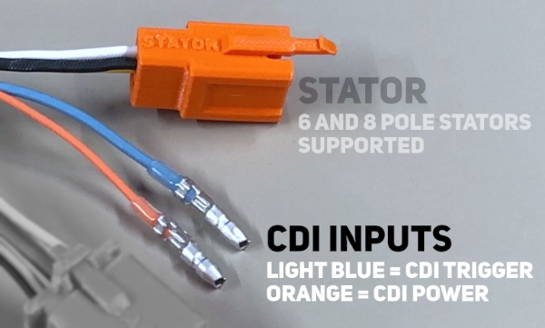
The SuperGY6 harness is capable of running either an AC CDI or a DC CDI without internal wiring changes. The ORANGE bullet wire is CDI power. Where you connect orange determines which version of CDI you can use.
- AC CDI: Connect the orange wire to the RED/BLACK wire from the stator.
- DC CDI: Connect the ornage wire to a 12-volt DC power source, behind a separate switch.
DC CDI note: The harness will still kill a DC CDI via the kill switch, and will still disconnect CDI ground via the key switch in "OFF" position. Some DC CDIs in our testing didn't require an external switch on the positive side. Your results may vary depending on the DC CDI you select, be sure to test and confirm before use.
For best results, we recommend using the AC CDI included in the SuperGY6 parts kit. It is uncomplicated, reliable, and supports good ignition current through the full rev range of the GY6.
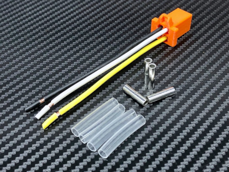
¶ Missing old stator connections?
If your stator connections are missing, or wires are getting discolored beyond recognition, it's probably time to go ahead and replace the stator. If the stator is tested and otherwise known to be good, you can grab a stator pigtail kit to avoid cutting the harness.
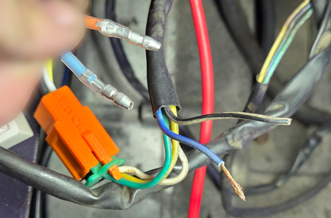
Here are the connections:
Bullet connections:
1. Orange   --->   Stator Red/Black (can appear faded white/black if old)
2. Light blue ->   Stator Blue/White

Square connector:
3. Yellow   --->   Stator Yellow
4. White    --->   Stator White (Sometimes pink)
5. Black    --->   Stator Green (Ground)
-
If you're missing the red/black wire from the stator, you may either run a DC CDI per instructions above, or swap your old 4-wire stator over to the normal 5-wire stator.
If you need new bullet connections for your stator, grab a pack of 4mm (3.9mm) female bullet terminals to make it easy.
⛔ Cutting off the harness connector is not an acceptable solution to save an old stator. The stator connection is one of the most important points in the system for long term reliability and ease of maintenance. Removing it creates unnecessary room for error and hassle when replacing the stator later. If your stator connector is missing or the wires are damaged, replace the stator or repair the stator-side connector. Do not modify the new harness.
¶ Chassis Routing to Dash
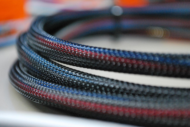
The harness is lengthened and intended to be routed along the DRIVER SIDE of the frame. Use the included wire ties to secure the long harness section to the inward-facing side of the frame tubing where the driver's knee rests.
This is the best routing method to reduce the chance of snags from passing branches or careless feet. It also keeps the wiring dry and prevents it from resting in mud, water, or other contamination.
Floorpan routes should be avoided unless absolutely necessary, such as with a UTV-style frame. UTV frames also require the 4FT extension, sold separately.
DO NOT attempt to route along the passenger side for any reason.
DO NOT attempt to cut and "tuck" the harness inside the frame tubes.
¶ Switches
¶ Key Switch Pinout
The key switch has numbers on the back, either 1, 2, 3 or I, II, III. We ran a marker over the text here for the picture. These numbers are usually the same color as the plastic, so you have to look closely.
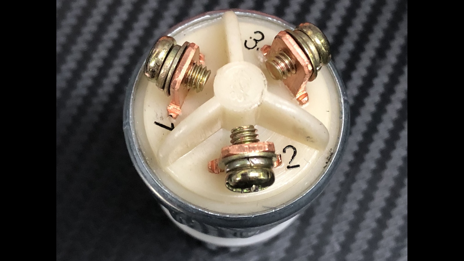
CORRECT ORDER:
1 - BLACK RING
2 - BROWN RING
3 - BLUE RING
NON-STOP CRANK WITH KEY ON? If you miswire the key switch, the starter will begin cranking any time the key is turned to ON.
Correct the wiring immediately by ensuring blue is on tab #3. Look closely at the numbers and make sure you don't confuse tab #2 for #3.
¶ Kill Switch Operation
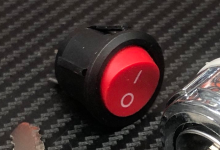
Switch may come either red or black.
When the kill switch is ON, the engine is killed by grounding out spark. This is why the kill switch must be turned OFF for the engine to run.
Beware of confusing advice online:

Although this statement correctly calls it a kill switch, the commenter appears to mistakenly treat it as an "engine run" switch. We have never seen a confirmed case of incorrect toggle-switch printing, so misunderstanding the kill circuit function is the more likely explanation in this instance.
To explain more clearly: the kill switch is not an "engine run" switch. It is a fully separate backup method of stopping the engine in case the key (or key wiring) malfunctions in a way that fails to shut the engine off. It is called a "kill switch" because it only has one dedicated job: to kill the engine. The switch is labeled accordingly.
If the kill-switch were printed in reverse, as the comment seems to suggest, the result would be a backwards setup that would not make sense for most users. A kill switch should be turned OFF to allow the engine to run without confusing its functional role.
TLDR: Kill switch ON ("I" position) kills the engine. OFF ("O" position) allows the engine to run. It is not a "run" switch; that's the key's job.
We don't cut corners to implement the kill feature. Your SuperGY6 harness has two completely separate wires running from the engine to the dash, with the ability to kill spark and stop the engine by two different methods. This is done for safety and redundancy.
Some online "experts" suggest using a single shared wire for both the key switch and kill switch back to the CDI. We do not recommend that approach because it undermines the role of the kill switch if that single wire develops a problem. The SuperGY6 harness keeps these circuits separate so the kill function remains redundant and reliable.
¶ Fresh install issues
¶ "Installed and no spark!"
If you're not getting spark after a fresh installation, the answer is the same across these three scenarios:
- No spark at all
- Only one spark when letting off the key
- Spark only lasted one or two rides
Assuming everything is installed correctly and your kill switch is OFF, but you don't have spark:
YOUR STATOR VOLTAGE NEEDS TO BE CHECKED.
Grab a multimeter and set it to read AC voltage. Test the RED/BLACK wire from the stator while cranking the engine over.
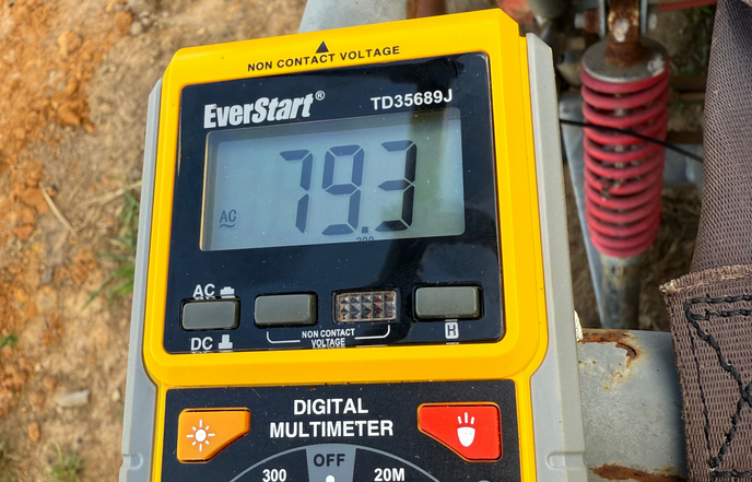
IF YOU SEE LESS THAN 100 VOLTS AC, THE STATOR IS TOO WEAK FOR RELIABLE SPARK AND NEEDS TO BE REPLACED.
New stators should read 120v to 150v while cranking.
This is an example of bad stator voltage:
Why is 100 volts from the stator necessary?
Well, going back 20 years or so, earlier CDIs were much more tolerant of low and weak stator voltage. Some would work on as low as 18 volts AC from the stator.However, there's often a big difference between "it works" and "it works well." What you should understand is that if stator voltage is weak, then spark will ALSO tend to be weak at the plug, often prone to blowout under compression while actually running in the engine. This can result in poor, unreliable ignition with symptoms that are misleading and difficult to track down, often seeming more like a carburetion or compression issue when it's just a bad stator on its way out.
This is why we like the newer CDIs better. Life is much easier with a CDI gated to a 100-volt minimum: it produces strong spark when everything is healthy, or simply doesn't spark at all when the stator starts going bad. This results in much clearer pass/fail diagnostic states that help eliminate confusing "gremlins", which are now much easier to spot, fix, and support.
If you need a replacement stator, reach out for the latest recommended sources. There are many "brand new" defective F-grade stators dumped on Amazon, eBay, etc. which perform worse than 10 year old used units.
¶ Headlights
¶ Recommended Lighting Setup
This harness is designed so the headlights power on automatically with the engine. No headlight switch is necessary, and one should not be added.
We recommend keeping two halogen headlights permanently connected to the headlight circuit any time the engine is running. See below this section for rationale.
Total headlight wattage should be matched to stator size to reduce dimming and flickering at idle:
- 6-pole stator: 2x 35 watt bulbs / 70 watts total
- 8-pole stator: 2x 45 watt bulbs / 90 watts total
Keep your regulator reliable. Keeping the lights on while the engine is running reduces regulator heat and helps prevent excessive electrical stress on the voltage regulator. This gives the regulator the thermal margin it needs to survive hot days, especially when the battery is already full.
Don't disable auto-on headlight functionality unless you understand proper load-balancing techniques. Keep it simple, keep it automatic, and keep regulator lifespan and reliability high.
¶ AC Headlights for Reliability
The harness is wired so that headlights are powered by regulated AC from the stator. In this arrangement, the lights help use up stator output directly, without forcing that power through the rectifier side of the regulator/rectifier unit.
By using the lights to consume a significant portion of stator output before the regulator has to deal with it, the system can help keep average regulator temperatures lower and thus improve its lifespan in the field.
Keeping the lights on AC also eliminates the added heat and wasted power in the regulator/rectifier unit that would otherwise come from pushing headlight current through the rectifier diodes. So unnecessary conduction losses are avoided.
Beware light features that may create unintentional electrical pitfalls. Some later machines came from the factory with light switches and other manual controls that allow these loads to be shut off or reduced while riding. While these extra controls may have been intended to be helpful to the end user, we consider them a step backwards for electrical reliability in the field.
Running the system with the headlight load switched off or reduced can increase regulator and stator stress, which may shorten their lifespan depending on operating conditions, particularly on hot days. We believe this can be one of the factors that contributes to repeated regulator, stator, and charging-system failures on GY6-powered karts, along with the frustration those failures cause for owners.
Keep reliability simple: keep the lights on and correctly loaded for your stator type.
¶ Headlight Troubleshooting
Headlight voltage is regulated AC from the stator, not 12-volt DC. It is normal to see 0-volt readings while the engine is off, regardless of key position.
Make sure headlights are connected before testing or operating the system. Multimeter readings can appear unusually high, erratic, or unregulated at the headlight leads without a load connected to stabilize stator output.
If your lights dim or flicker at idle, it's generally the case that the total lighting load is too high, or the stator is weak/degraded. Reduce the light load or replace/upgrade the stator.
Practical testing procedure:
If your lights are dim, use this process to get a practical idea of what the stator can support at idle without needing to use a meter.
- Connect all lights, then start and idle the engine.
- Shut the engine off and disconnect one light.
- Restart the engine and check whether the remaining lights shine brightly.
Repeat steps 2-3 until the connected lights stay bright at idle.- Shut the engine off. Check the wattage rating printed on all bulbs that are still connected and add them up.
The total wattage you add up in step 4 is a practical estimate of what your stator can support at idle. If the amount of lighting available at this point is less than desired, consult the service manual for your vehicle to determine whether the stator is out of spec. If the stator is within spec, consider upgrading it to support more lighting.
This test is done at idle because that is when its generated output is lowest. Stator strength increases with engine speed.
Note 1: Older GY6 stators can be upgraded from 6-pole to 8 or 11-pole. Most newer engines come with an 8-pole stator from the factory.
Note 2: The harness, regulator, and battery usually have very little say in headlight brightness. In most situations, headlight performance comes down to the stator output, total light load, bulb condition, and wiring/connector condition between the stator and lights.
¶ Custom LED Headlights (DC)
DO NOT use LED lights on the yellow and black headlight wires. LED lights are not compatible with this AC headlight circuit. The yellow and black wires are for the AC halogen headlight circuit only. Scroll up for recommended lighting setup.
LED lights should be treated as a custom DC lighting setup, not a plug-in replacement for the expected halogen load.
If you wish to use LED headlights, they must be wired separately to battery DC on their own fused circuit, relay, and switch, and must be sized appropriately for your stator output.
Running LED headlights separately on DC may work, but it bypasses some of the simple reliability built into the harness. You must still make sure the system has the correct total electrical load, and that the regulator is not being overheated by running without the intended AC headlight load.
¶ "Bigger battery for lights?"
When folks run into low stator or lighting output, we've seen commenters online suggest "just get a bigger battery and run the lights you want on DC". This is often misleading and can create a worse experience.
That advice ignores the extra heat generated inside the regulator/rectifier when you ask it to convert more AC power into DC power. The rectifier and regulator are inside the same unit, so extra DC lighting current means more heat in the same small housing.
Wiring lights on DC does not magically remove stress from the regulator/rectifier. It can do the opposite by shifting more workload onto the rectifier side, especially when paired with a larger battery and a stator that may already be underperforming or too small.
Our AC lighting circuit helps avoid this by letting the headlights consume stator output directly, before that power has to be handled by the regulator/rectifier unit.
AC headlight power is still regulated to prevent bulb over-voltage. The lights pull the power they need first, and the regulator only has to clamp excess voltage when engine speed and stator output rise high enough to require it.
It's an intentionally simple system that keeps things balanced and avoids overworking any single component.
Bottom line: A larger battery does not fix weak stator output. It only takes longer to drain while hiding the real problem.
¶ "Run without headlights?"
Running without headlights is okay for a few minutes of testing. It becomes a problem when the battery is full and there is nowhere useful for the stator output to go because no lights are connected, especially at higher RPM. This puts extra stress and heat into the regulator and can shorten its lifespan quickly.
DO NOT run the engine without headlights connected for prolonged periods, especially on hot days. Damage to the voltage regulator, connector, stator, or related wiring may occur due to overheating and excessive electrical stress.
¶ Brake-Start Interlock
The harness supports a brake-start interlock feature, where the brake switch must be activated before the engine can start. It works by disabling the starter solenoid unless the brake is pressed. Ignition is not affected.
Important: This harness ships with the brake-start feature pre-connected in bypass mode. Be aware that the engine may start without the brake applied unless you explicitly enable this feature (see below).
Because many adult owners choose to disable the factory interlock on their own karts, the harness is shipped with brake-start in bypass mode by default to keep installation simple while still retaining the feature for those who wish to use it.
To enable the brake-start interlock feature, locate the dark blue bullet wires just after the engine-to-chassis connection. Connect these two blue wires to your existing brake switch. Polarity is not a concern; either wire can attach to either side of the switch. An extension may be necessary depending on the model.
No-spark reminder: The brake-start interlock does not control spark. It only controls whether the starter solenoid can crank the engine. If the engine cranks but has no spark, the brake switch is not the cause.
Spark is never affected by the brake switch in this system.
¶ Additional FAQ
¶ "Best battery size?"
Stick to a 12 volt battery with a capacity rating between 6.5 amp/hour to 12 amp/hour.
¶ "No speedometer?"
The factory speedometer is not supported by this harness kit. The original speedometer assemblies are commonly unreliable, and don't justify the added harness cost required to wire them back in. Rather than increasing the kit price at USA rates to support a low-quality factory component, we recommend putting that money toward a quality aftermarket speedometer.
We recommend using a quality aftermarket speedometer instead. Units from brands such as Trail Tech or similar provide outstanding value per dollar, and typically include their own wiring, installation instructions, and product support.
¶ "No gear indicator?"
Our harnesses don't (and will never) support the gear indicator light feature. Factory gear sensors are often unreliable and prone to false indication of shift position.
Drivers have stripped gears and ruined transmissions after believing a faulty shift indicator, believing the transmission was fully in gear when it wasn't. Don't make this mistake.
Instead of relying on an inaccurate indicator light, it is best to form a good habit of blipping the throttle after each shift to ensure you're fully in gear, then start driving. Do not rely on cheap indicator sensors.
¶ "No turn signals, horn, brake light?"
Tried it. When we added these features in a trial run, people hated the more complex installation.
Fact is, these features don't add value for most people. Folks want a simple, reliable system with the easiest installation we can reasonably build into the design, plus low ongoing maintenance. That's it.
What you're paying for here is build quality and thoughtful design improvements over factory that allow a dead simple installation.
¶ So, it's all about reliability then?
Yes, reliability is the entire point. It's best to focus every dollar of your kit on core engine functionality, so the machine is easy to get running with a few minutes of installation and then continues to run for years without headaches from unnecessary complexity.
¶ Disclaimers
This product is sold "AS IS" and "WITH ALL FAULTS," without any warranty, express or implied, including any implied warranty of merchantability or fitness for a particular purpose. Installation, modification, troubleshooting, and use are performed at your own risk.
The manufacturer and seller assume no liability for damages, including but not limited to personal injury, equipment damage, electrical damage, fire, loss of use, loss of income, towing, recovery, replacement parts, labor costs, or property loss arising from use, misuse, improper installation, troubleshooting, modification, or failure to follow instructions.
Any statements, diagrams, warnings, recommendations, or guidance provided by the manufacturer or seller are for general informational purposes only and should not be construed as professional, expert, mechanical, electrical, engineering, or safety advice. The installer and user are solely responsible for verifying proper fitment, routing, grounding, fuse protection, connection security, clearance from heat, moving parts, sharp edges, and safe operation before use. Use at your own risk.
⚠️ WARNING: This product can expose you to chemicals which are known to the State of California to cause cancer. For more information, go to www.P65Warnings.ca.gov.